GAS TURBINE AND RECIPROCATING
ENGINE DECISIONS
UPDATE
September 23, 2016
McIlvaine Company
TABLE OF
CONTENTS
McIlvaine
September 5 Noise Reduction Interview with Dennis G. Aaberg
Clarcor to Become Sole Supplier of Inlet Filtration
Systems for GE’s H-Class Gas Turbines
GE and Tata Collaborate to Reduce Gas Turbine
Manufacturing Cost
Houweling’s will Install Two 4.4 MW GE Engines in BC
Greenhouse
Houweling’s is also Operating GE Engines at is
Camarillo California Plant
PacifiCorp Activities to Receive Special Coverage in
GTRE Decisions
Currant Creek Plant is CHP with Successful Tomato
Growing Operation
Energy Saving Projects at Washington Plants
Dennis Aaberg has recently retired from Cummins Power Generation after a
thirty-seven-year career in noise and vibration control. He is a recognized
expert on the subject and the author of articles appearing in our Gas
Turbine, Reciprocating Engine Decision Guide. During his career, which
began with Onan Corporation before it was purchased by Cummins, Inc. and became
Cummins Power Generation, he worked within the Applied Technology Group to
reduce product noise levels and improve sound quality on small gas and diesel
engines, generator sets, garden tractors, welders, and a variety of other
engine-driven applications. Dennis has also worked integrally with
customers to solve community noise issues, and application noise issues.
Dennis’ acoustical and vibration knowledge has developed through hands on
experience working on engineering projects and research experiments over that
thirty-seven-year period and attending seminars and classes at such higher
education outlets as Massachusetts Institute of Technology, Purdue University,
University of Wisconsin, University of Minnesota, and numerous other seminars
taught by industry experts and data acquisition equipment manufacturers.
Dennis agreed to answer our specific questions.
McIlvaine:
What are the advantages of customizing
silencer solutions?
Dennis:
To provide fairly accurate insertion loss predictions (i.e. within 1-3 dB(A) or
better) for a given internal combustion engine driven product the silencers must
be custom made for each engine driven application because a given muffler will
perform differently for each different engine it is integrated with.
Exhaust silencing systems act as a system with
the engine, so any modeling work must include physical internal dimensions of
the engine exhaust system and engine; along with all the engine operating
parameters. That is partially why when you look in exhaust silencer
manufacturer catalogues you typically see a 10 dB(A) expected exhaust noise
insertion loss range, because it can vary greatly from engine to engine.
Therefore, to custom design a product to meet a strict noise level, several
iterations of modeling, analysis, test, and validation typically need to be
made. This can be time-consuming and expensive, but perhaps necessary in
critical noise control applications; which are becoming much more common
globally.
Since the speed of sound changes with
temperature, this can also complicate the expected insertion loss of the muffler
for any particular engine because the broadband effectiveness of the silencer
can vary as the engine exhaust temperatures change as the silencing
effectiveness at various frequencies can change as the engine and silencer
temperatures change.
That is why reputable design and test facilities
allow and engine to stabilize at each load and speed for approximately 15
minutes typically before measuring the sound levels.
McIlvaine:
The CO2 from engines is particularly beneficial for
greenhouses. What noise challenges does this pose?
Dennis:
I am not familiar with using CO2 from engines for greenhouses, but I
do know that emissions regulations are getting increasingly stricter to reduce
CO2 emissions.
Exhaust silencing systems have been, and are
continuing to be developed to reduce exhaust gas emissions. These systems
require extensive design considerations, involve using chemical injections into
the diesel exhaust gas stream, and are very expensive; but they are becoming
available.
McIlvaine:
How do noise regulations vary around the world, and how strict are they?
Dennis:
In North America, sound levels are regulated at property lines. Therefore,
when selling products, the sales force must rely on the company providing
accurate sound levels for the products, and when the capability exists,
predicting sound levels at the property line for the application so they can
avoid any fines or loss of sales due to not being able to meet the noise
regulations. (Side note: I used an environmental noise modeling
program called SoundPLAN for this purpose in several situations. SoundPLAN
is generally accepted globally as the premier software modeling program for this
purpose)
In the European Union, and generally in other
parts of the world, sound levels are regulated at the source: meaning the
products up through 400 kW cannot be sold into the European Union if they exceed
the regulated noise limits, specified in A-weighted Sound Power Level (i.e.
dB(A) Lw, or SPWL).
In India, generator sets for outdoor
installations must be installed in a sound enclosure, and the sound levels
measured 1 meter from the generator set cannot exceed 75 dB(A). This is
regulated by their Pollution Control Board.
Noise is increasingly becoming a more sensitive
issue globally and regulations globally are driving acceptable noise levels
lower. Therefore, going forward companies selling products that are
regulated by noise ordinances, regulations, and laws will want to invest in
staff, equipment, and software to effectively and efficiently design their
products with high confidence levels that their final production products will
meet the required sound levels in the markets they plan to sell in to.
McIlvaine:
What are some noise reduction considerations for recreational vehicles and
boats?
Dennis:
Everything has natural frequencies that they like to vibrate at, including
humans. When input forces match the natural frequencies things go into
what we call resonance. These are frequencies where energy is easily
transferred and accepted and can cause the vibrating object to move violently
and fatigue sometimes very quickly and break. At the very least, it will
cause more than usual noise caused by the vibration, since sound is simply
pressure variations caused by vibration in an elastic medium. The higher
the levels of vibration: the higher the noise level.
Recreational vehicles and boats tend to have
large lightly damped structures that like to vibrate at low frequencies.
Generator set primary operating speeds many times line up closely with these
natural frequencies so great care must be exercised in the placement of the
generator set and providing a large impedance mismatch between the generator set
and boat or recreational vehicle structure to provide the isolation necessary to
keep the energy transfer to a minimum. This is usually a challenge and can
be very difficult.
If not critically isolated or if placed in a
part of the structure that is particularly receptive of force inputs, the
vibration forces entering the structure can easily travel from one end of the
structure to the other and cause unacceptable sound and vibration levels inside
to the horror of the people inside the vehicle or boat. As with all
applications, this is a system problem that is best resolved by manufactures of
the boats, recreational vehicles, and generator sets working together to solve
the system problem effectively and efficiently as possible. This can be a
challenge, but is the best approach.
McIlvaine:
What about sound quality? When does that become a
factor?
Dennis:
Sound quality over the past twenty years or so has become increasingly more
important in Consumer Product Markets, such as the recreational vehicle and
marine applications. I have witnessed cases where overall sound levels of
a product acceptable to the customer are higher in amplitude than ones that are
not acceptable simply due to the quality of the sound.
Increasingly owners of recreational vehicles and
boats are saying they don’t want to hear their generator set operating.
They want to flip a switch and get power but not the noise of the generator set
to go with it. As with most things, we want everything, but we are only
willing to pay for so much. This is where sound quality becomes especially
important. If we can improve the quality of the sound to be unobtrusive
even though audible, the customer is willing to accept that.
I might also add that it is possible to design
an application in such a way that the generator set would be silent in respect
to the natural ambient sound levels, but it requires larger sound enclosures,
and almost certainly use of “active sound and vibration systems” that cancel the
acoustic and vibration signals going into the structure by monitoring the signal
and sending a signal back 180 degrees out of phase to cancel it. Since
active cancellation systems are still fairly expensive as compared to passive
systems, most customers are not willing to pay for that increase noise
attenuation yet, but the option exists.
Also, since internal space availability in boats
and recreational vehicles is a premium for customers, they are not yet willing
to sacrifice the space for less noise. Perhaps in the future this will
change as the population gets progressively accustomed to lower noise levels in
the environment. As with everything in life, as higher expectations are
satisfied it just drives expectations even higher.
McIlvaine:
What are considerations for engines and generator sets installed inside a
building or on a building’s roof?
Dennis:
If installed in buildings, the primary considerations are air flow silencing for
the room inlet and outlet air systems. Typical installations have the
generator sets mounted on isolation springs of properly designed stiffness to
reduce vibration energy from transmitting through the floor to the building
structure: or in the case of roof-mounted generator sets, transmitting through
the roof to the building structure.
If installed in a building’s room, the wall mass
usually provides the necessary transmission loss, especially if the walls are
sand-filled, which they many times are to provide the extra mass and damping
needed for good sound transmission loss.
Another consideration is the exhaust silencer
system. These systems typically are designed to run vertically above the
building’s roof level, so they must consider the backpressure produced in
overcoming the pressure to push the exhaust gases up the silencer’s piping
system and how that affects the generator set’s available power output.
McIlvaine:
There seem to be a variety of designs, costs, and performance of sound
enclosures. What tips do you have for purchasers?
Dennis:
There are a wide variety of sound reduction enclosure offerings depending on the
installation sensitivity to sound.
The very basic sheet metal enclosure that is
meant to simply protect the unit from the weather may have louvered openings all
around and no sound reduction materials or sound reduction ductwork. These
relatively flimsy enclosures, in vibration terms, may even increase noise levels
because they are not designed to be noise reduction enclosures, and they will
typically vibrate enough to cause an increase in overall sound level, or at
best, provide no sound attenuation.
Above that, there are typically several levels
of noise reduction offerings based on application needs. These range from
approximately 10 dB(A) reduction to over 20 dB(A) reduction or more in the case
of well-designed drop-over sound enclosures that provide the necessary space to
design high transmission loss walls and high noise reduction air inlet and
outlet ductwork. A 10 dB(A) sound attenuation enclosure with sound
absorption material, a medium grade exhaust silencer, and relatively
unsophisticated air inlet and outlet ductwork for air-flow is usually attained
without much effort.
I must add, however, that all sound attenuation
enclosures must be designed, tested, and analyzed by competent engineering staff
to ensure especially that the cooling capacity needs of the generator set are
maintained to prevent overheating and reduced power output.
McIlvaine:
Can cooling systems add to the noise problem in an enclosure?
Dennis:
As power density increases in generator set products, cooling system packages
are many times producing higher sound levels than the generator set
(engine/generator). This has resulted in the difficult position of
providing a sound enclosure in a reasonable skid-mounted size that can
effectively reduce the noise of the cooling system, which tends to generate high
sound levels at typically low blade-pass frequencies that can be difficult to
attenuate without long acoustically treated air flow ducts.
This is another reason why companies producing
such products can benefit from a staff with good acoustical sound attenuation
knowledge, state-of-the-art data acquisition and analysis equipment, acoustical
modeling expertise, and facilities capable of performing accurate acoustical
measurements in accordance with ISO requirements and recommendations.
McIlvaine:
Any other tips for sound enclosure purchasers?
Dennis:
Keeping in mind that sound is vibration in an elastic medium, and the fact sound
enclosures have large, flat, and usually lightly damped structures, enclosures
are especially susceptible to any vibration paths from the generator set to the
sound enclosure and skid base they are mounted to. Short-circuit paths can
greatly reduce the effectiveness of an otherwise well-designed sound enclosure.
Short-circuits include anything that connects
directly from the operating generator set to the enclosure: such as ground
cables, stiff hoses, exhaust piping touching walls they pass through, vibrating
cables, any compression points between acoustical sound absorption insulation
and the generator set, and etcetera.
Excessively stiff isolation mounts between the
generator set and skid base is another factor. The isolation mounts should
be as soft as possible while still providing sufficient load capacity.
Orientation and location of the isolation mounts can also be a significant
factor.
Skid base stiffness is also an important
consideration. It is prudent to determine the natural frequencies in the
skid base and design a skid base with proper stiffness to avoid natural
frequencies that coincide with the operating frequencies produced by the
generator set.
Clarcor has entered into a ten-year agreement with GE to
become the sole filtration supplier to its H-class power turbine.
The agreement also has provisions for Clarcor to work with GE in
developing the next generation air inlet filtration system for the H-class
platform. GE’s H-class gas turbine
is one of the world’s largest and most efficient turbines in the business.
Clarcor had acquired the air filtration business from GE in December
2013, and it has worked for nearly a year to clinch this deal.
Clarcor will be
providing filters and other components to GE at a discount to cost.
The company expects to realize a sizable aftermarket benefit starting
four years after the sale of the original equipment.
Powerphase, a developer of upgrades for gas turbines, has
been issued a U.S. patent for a technology that improves the output, fuel
efficiency and responsiveness of gas turbines operating at high ambient
temperatures or elevations.
The technology, Turbophase, uses a fuel driven engine and
its waste heat, along with a highly efficient compressor in a cogeneration
process to generate hot, compressed air approximately 35 percent more
efficiently that the gas turbine itself.
The highly efficient air is then injected into the gas turbine, allowing
it to produce its optimum output in all ambient conditions.
Because the incremental air is created so efficiently, not only does the
gas turbine generate more megawatt hours, but it also makes all of its megawatt
hours more fuel efficiently.
The company has installed Turbophase on the two most widely
used gas turbines, the 6B and the 7FA, both manufactured by GE.
Because all gas turbines use copious amounts of air in their combustion
processes, greater air efficiency leads to greater fuel efficiency.
"Our innovative use of air creates a generational leap is
gas turbine fuel efficiency,” says Bob Kraft, the inventor of Turbophase.
“We like to say, 'Air is cheaper than fuel.'"
GE and Tata Consultancy Services have developed a
technology that will revolutionize the gas turbine manufacturing process using
smart LEDs and GE’s Predix operating system.
The solution will analyze temperatures at various points on the metal
turbine parts as they are assembled and cooled, allowing operators to know when
the next operation can be performed, reducing wait time between operations and
improving quality monitoring. A pilot application has been built at GE Power’s
gas turbine manufacturing plant in Greenville, South Carolina.
During the turbine manufacturing process, rotor stacking is
a key process and needs extremely high levels of precision.
If the rotor wheels are stacked incorrectly due to differences in the
surface temperature, it will require reassembly, incurring heavy additional
costs and two to three weeks of shipment delays.
Tata’s new digital solution provides automatic data collection of ambient
room and rotor surface temperatures, notifying workers when the next operation
may proceed and alerting workers to any non-uniformity.
The platform is composed of smart LED fixtures from
Current, powered by GE, integrated with sensors that monitor temperature,
humidity and any physical object presence, transmitting the data to an Intel
Atom-based gateway where the information is streamed to the Predix cloud.
GTRE second section
Houweling’s Nurseries Ltd. (dba, Houweling’s Tomatoes)
operates a 20-hectare greenhouse facility in Delta, B.C., producing both fresh
tomatoes and propagated vegetable seedlings for other greenhouse vegetable
growers. The heat and CO2
requirements are supplied by five natural gas fired boilers which have an
estimated efficiency of approximately 84%. The estimated emissions produced by
the current operation of the natural gas fired boilers are 23.7 tons annually.
The boilers operate throughout the day to produce heat
which is stored in a 1.5-million-gallon reserve tank and subsequently used as
required in the greenhouse. Some amounts of the CO2-enriched exhaust are used to
promote a healthy crop and vegetable production.
An additional 1,000 tons of liquid CO2 is purchased for their
seedling propagation department, as the CO2 generated from the
current system is not acceptable for growing seedlings.
This limitation creates additional waste during the months
of October to February as crop production is reduced and seedling propagation is
at its peak production. During this
period the boilers are only in operation for heating generation. As a result,
the exhaust from the boilers is released into the atmosphere, while liquid CO2
must still be purchased.
Houweling’s Tomatoes proposes the installation of two 4.4
MW GE Jenbacher natural gas-fired, combustion engine driven, cogeneration units.
The CO2 enriched gases from the engines will be treated using
selective catalytic reduction (Hanwel COdiNOX system) to reduce the NOx
levels in the exhaust, meeting the requirements of the seedling crops as well as
promoting healthy crop enhancement in the tomato production area. This flue gas
cleaner ensures the flue gases from CHP gas engines are converted into food
grade CO2, which can then be used immediately for plant and seedling
fertilization. This will eliminate the need to purchase, transport and store
liquid CO2. The anticipated emissions from the Co-Gen units will be
less than 11.5 tons annually, reducing emissions output by at least 50 percent.
GE engines have been providing heat, power, and CO2
to a California greenhouse for the last several years. Houwelings Tomatoes, is
operating the first combined heat and power (CHP) greenhouse project in America
that captures carbon dioxide (CO2) for use in plant fertilization.
Using two of GE’s 4.36-megawatt (MW) units, Jenbacher J624 two-staged
turbocharged natural gas engines and a GE-designed CO2 fertilization
system, the plant provides heat, power and CO2 to Houwelings 125-acre
tomato greenhouse in Camarillo, Calif.
GE has installed more than 800 gas engine CHP units in
greenhouses globally. This represents approximately 2 gigawatts of power
generation plus CO2 fertilization systems. With the installation of
Houwelings engines GE has its first U.S.-based system.
The first greenhouse CHP project in the U.S. also gives an
added boost to California’s goal to generate 6,500 MW of new CHP generation in
the state by 2020. The project represents the launch of GE’s J624 two-staged
turbocharged gas engines for the 60 Hz segment and the first of these engines
sold in the U.S. Introduced by GE in 2007; the J624 is the world’s first
24-cylinder gas engine for commercial power generation and can be used in
various applications. It also is the first gas engine featuring double turbo
charging, which makes it even more efficient.
McIlvaine has been conducting a series of five webinars for PacifiCorp to help
them with their decisions on NOx control at coal-fired power plants.
The webinars are organized around the information which is gathered for Power
Plant Air Quality Decisions. This
effort is being expanded to cover activities at all the PacifiCorp power plants.
The purpose of adding information on PacifiCorp gas turbine and gas engine
activities is to demonstrate the value of GTRE Decisions to any power plant
Person
to person communication optimization is just as challenging
as machine to machine. Suppliers and consultants as well as individuals
within PacifiCorp can benefit from the communication regarding
activities at all the plants.
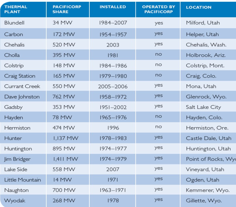
All the newer thermal power plants operated by the company are fueled
with natural gas.
An upgrade was
supplied several years ago. We would like to report on the current status
and include options by one and all on the approach.
The Currant
Creek project is a grassroots 525-megawatt natural gas-fired power plant
consisting of a 2 x 1 combined cycle power block. The plant was constructed in
two phases: Phase 1 consisted of the installation of two GE 7FA combustion
turbine generators to operate in simple cycle mode, and Phase II called for the
installation of two heat recovery steam generators (HSRGs) and a steam turbine
generator.
The two HRSGs
constructed in Phase II were a 10-module tube bundle design. PCL’s work included
installation of the Low Pressure (LP), Intermediate Pressure (IP), and High
Pressure (HP) steam drums, boiler piping, soot blowers, platforms, grating, and
associated equipment.
PacifiCorp entered into a sole source
contract with General Electric International to install its Op-Flex cold day
performance package on the Currant Creek plant. The estimated amount of this
purchase is $7,819,500.
Under the contract
General Electric was to provide three equipment packages designed to increase
the cold weather performance, gas turbine operational flexibility, increase base
load output, and enhance combustion dynamics monitoring at the Currant Creek
plant. The “Op-Flex Cold Day Performance” package is designed to provide
increased output and improved heat rate during cold weather conditions.
The “Op-Flex Turndown” package provides the ability for plant turndown
(reduction in load) to be reduced from 80% to 70%. This package will
result in lower operating costs, increased low load reliability, less fuel
consumption to stay on line, and expanded emission compliance. The
“Continuous Dynamics Monitoring” package enables the first two packages to work.
PacifiCorp said that
they had exhausted competitive alternatives to the engine control packages
offered by General Electric. These packages can only be provided by
General Electric, the original equipment manufacturer and owner of the
proprietary engine control system. Payment for the equipment packages is
based on a sliding scale based on performance. If the unit performance
meets or exceeds the guaranteed performance levels, payment will be at the level
stated above. If unit performance does not meet the guaranteed level, the
payment is reduced accordingly down to a minimum level of $319,500.
If you have any
contributions to update us on this, it would be appreciated.
The Currant creek plant
provides heat and CO2 to a large on site tomato greenhouse. It
involves a large duct providing waste heat and CO2 as shown in the
picture below. It has been quite successful but one Pacific Corp source
said that in the future the hot water from the HRSG a smaller duct with just
enough flow to provide the CO2 would be an even better solution.
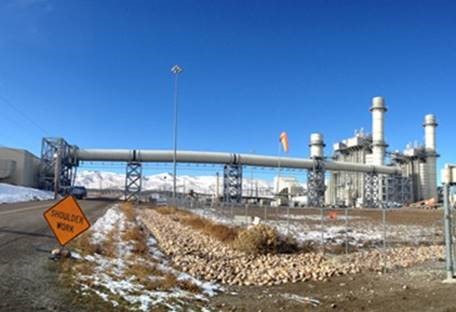
A duct connects Rocky Mountain
Power's Currant Creek Plant with the Houweling’s Tomatoes greenhouse. The power
plant heats the greenhouse and it provides nutrients and condensed water to the
tomato plants.
The 28-acre Houweling’s
Tomatoes greenhouse near Mona, Utah, is among the first of its kind in the world
to draw its heat and plant-nourishing carbon dioxide from a neighboring power
plant. A bonus for Houweling’s is the water it condenses from the flue gas is
used to irrigate the tomato plants.
Brad Richards, manager at Rocky
Mountain Power’s Currant Creek Plant explained, “The manufacturer of the boiler
and stack engineered the penetration in the stack and determined there wouldn’t
be any issues with our operations or with our emissions monitoring equipment.”
A plant outage was required to
complete construction of the duct. So Houwelings and Rocky Mountain Power
coordinated the work during planned maintenance on a weekend in April 2015.
The Houweling’s Tomatoes heat
recovery system inside its boiler building connects to the 10-foot-diameter duct
from Currant Creek Plant.
“We’ve been upfront with
Houweling’s from the beginning that our customers are first priority with
everything having to do with safety and plant operations,” said Ian Andrews,
Rocky Mountain Power resource development director. “We had to coordinate a
phased construction process to work around the plant’s planned outage schedule.”
Houweling’s began construction of
the 475-foot-long duct from the plant to the greenhouse in July 2015. The
10-foot-diameter duct stands 25 to 30 feet above the ground.
“We didn’t expect any effects on
plant performance or reliability, and there haven’t been any,” Richards
reported. “The system is working well and was designed with very few changes to
our normal operation.”

Using an Argus control system, waste exhaust is drawn off
the side of the stack, diverting it into Houwelings energy building where
thermal energy is captured and stored for on-demand heat. Condensation from this
process is captured and used to supplement irrigation water, and the remaining
exhaust CO₂ is released directly into the greenhouse to promote plant growth.
The custom Argus system controls the equipment that extracts the CO₂ and the
heat from the stack gas and sends signals to and from the power plant, including
general status, alarm points and portions of dampers, CO₂ demand, boiler status,
and temperature and efficiency readings. The control system also monitors gas
flow and temperature, concentration of CO and NOx, and controls the condenser
fans, condenser pumps and dampers on this project.
Yurij Duda, Argus Controls General Manager congratulated
Houweling’s on the award: “Houwelings is a real leader in sustainable
agriculture and is truly committed to innovation in energy management. Argus was
honored to be selected as their control system partner to help make this unique
project a reality.”
The purpose of a 2011 report
was to outline the systems investigated and detail the cost effective measures
at three of the seven locations: Jim Bridger (Unit #1 only), Chehalis and
Goodnoe Hills. This 2011 report is displayed in full in the PPAQD
Intelligence System.
One of the biggest potential improvements at the time of
the report was adding VFD to pumps and fans. For example, VFD could be installed
at Jim Bridger for RO feed and condensate pumps.
This system consists of three
RO system trains; A, B and C. Trains A and B utilize three 60 HP RO feed
pumps and train C has two 75 HP pumps. Trains A and B use a discharge
control valve to deliver about 270 gpm of filtered water to the RO membranes.
During normal operation two of the three trains are in operation. When
Trains A and B are in operation only 2 of the three pumps are needed.
Train C only needs one of two pumps to operate.
Proposed: RO feed pumps on
Trains A and B should be upgraded with VFDs and controls to vary pump speed to
deliver the required flow to the RO membranes.
This measure would add the
following equipment:
·
Six 60 HP pump VFDs
·
VFD controls
Condensate Pumps
Baseline: The condensate pump system consists of three 700 HP 7,200 volt pumps
that transport condensate from the discharge of the main turbine to the
Deaerator (DA) tank.
During normal operation two of
the three pumps are needed to maintain the tank level in the DA tank. Two
parallel discharge control valves are modulated to the desired DA tank level.
Proposed:
The proposed changes would install new
inverter rated motors with VFDs and necessary controls to regulate the pump
speed. The pump speed will be varied to maintain the DA tank level. The existing
control valves should be fully opened during normal operation.
This measure would add the
following equipment:
·
Three 700 HP 7,200-volt pump VFDs
·
Three 700 HP 7,200-volt inverter duty motors
·
VFD controls
Forced Draft Fans
Baseline: This system consists of two 2,250 HP 7,200 volt centrifugal fans that
operate in parallel to provide secondary and overfire combustion air to
the boiler. Capacity control is achieved by variable inlet vanes. The
fans maintain a static pressure of approximately 16 in WC in the duct.
Both fans are needed during normal operation.
Proposed: The proposed ECM is
to install new 7,200-volt invertor duty motors and VFDs with controls. The
existing inlet vane dampers should be removed and speed control used to meet the
required flow and pressure based on unit load. This measure would add the
following equipment:
·
Two 2,250 HP invertor duty 7,200 volt motors
·
Two correctly sized VFDs
·
VFD controls
Other pumps and fans were included.
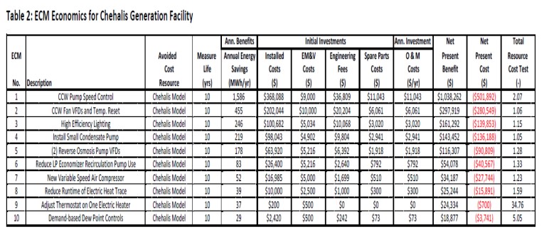
Also included is
the analysis for the520 MW gas turbine combined cycle plant located in Chehalis.
Approved gas turbine component supplier list for
PacifiCorp
Preferred vendors based on the
Currant Creek 2 plant are designated. For example, Cuno is the approved supplier
for the condensate filters. However, in 2011 at Wyodak the Pall filter was
installed to replace the existing Cuno string wound filters and positive results
such as less iron deposition were experienced. Has this information been
transferred to those making up bidders’ lists?
Here are new entries in the GTRE Decisions. You can click
on the title for the full text.
Wartsila has many applications in baseload, standby and emergency power
Applications include airport installations with heat, cooling, and power. One
installation is run with vegetable oil as a fuel and does include SCR. CHP
provides up to 90% efficiency.
Revision Date: 9/7/2016
Tags: Wartsila, NOx
Oil & Gas Slides - Hot Topic Hour August 26, 2016
The Oil and Gas webinar conducted by McIlvaine was primarily focused on the
opportunities created by the growth of gas by over 50 quads over the next 25
years.
Revision Date: 8/26/2016
Tags: 221112 - Fossil Fuel
化石燃料, 324110 - Petroleum
Refineries 石油精炼
Oil & Gas Webinar - Hot Topic Hour August 25, 2016
Maximizing flow control and treatment revenues is a volatile market.
Revision Date: 8/25/2016
Tags: 221112 - Fossil Fuel
化石燃料, 324110 - Petroleum
Refineries 石油精炼
Lower emission limits for biogas engines in SCAQMD as of January 2016
SCAQMD rule for biogas effective 2016 limits emissions to 11 ppmv NOx – 30
ppmv VOC – 250 ppmv CO. Stakeholders have commented that the capital and
operating costs for cleaning up the biogas are very high and post-combustion
control technologies such as Catalytic Oxidation and Selective Catalytic
Reduction (SCR) are expensive to install and operate and argued that many of
them will resort to flaring as a less costly alternative. Response: •The costs
are significant but the environmental benefits are also significant. •Proposed
controls are very cost effective. •Reasonable emission reductions such as those
from biogas engines needed to meet the ambient air quality standards. •Flaring
of a renewable energy source is undesirable. •Biogas flaring, except for a small
Greenhouse Gas disbenefit, has a much lower criteria pollutant footprint
compared to biogas engines, even considering power that needs to be generated by
central power plants.
Revision Date: 8/23/2016
Tags: 562212 - Solid Waste Landfill, Regulation,
SCAQMD, Emissions Control
Update as of March 2016: Following the Public Comment Period and Hearing of
July 2015, Microsoft submitted a revised permit application. The revisions are
currently under review. Upon a completeness determination, Ecology will provide
an additional public involvement opportunity for review and comment of the
requested permit revisions. When completed, the Oxford Data Center will contain
four Phase 1 activity zone (AZ) buildings designated AZ-4A, AZ-4B, AZ-4C, AZ-4D;
four core network room (CNR) buildings; an administrative building; and four
phase 2 AZ buildings designated AZ-3A, AZ- 3B, AZ-3C, AZ-3D. Building
construction for the Phase 1 generators and cooling towers began before the end
of 2014. Construction of Phase 2 is expected to begin within 18 months after the
start of generator commissioning for Phase 1. Project Oxford Phases 1 and 2 will
have thirty-two (32) Caterpillar Model 3516C-HD-TA diesel powered electric
emergency generators in the activity zone buildings with a power rating of 2.5
MWe per generator, four (4) Caterpillar Model 3516C-TA diesel powered electric
emergency generators in the CNR buildings with a power rating of 2.0 MWe per
generator, and one (1) Caterpillar Model C27ATAAC diesel powered electric
emergency generator in the administrative building with a power rating of 0.75
MWe. The engines are equipped to meet Tier 1
Revision Date: 8/23/2016
Tags: Microsoft Corporation, Industrial Emitters,
Data Center, Emissions Control
Multiple routes for siloxane removal from biogas
Cormetech cites low permissible levels of siloxane. Wastewater treatment
plants and landfills have higher siloxane levels. A variety of treatment methods
include consumables such as activated carbon, regenerative with resins, and even
chiller/adsorbers.
Revision Date: 8/23/2016
Tags: 562212 - Solid Waste Landfill, Siloxane,
Emissions Control
Johnson Matthey emission control for stationary engines
What is a catalyst? ◦ How does it work? �
Three Way Catalyst (aka NSCR or TWC) for Rich Burn Engines
� Catalyst Components and Operation
� Air-Fuel Ratio Controllers
� Summary
� Two Way Catalyst (aka Oxidation) for
Lean Burn Engines � Catalyst Operation
� Summary
� Selective Catalytic Reduction Systems
(aka SCR) for Lean Burn Engines � What
is SCR? / How it is Different from Two Way and Three Way.
Revision Date: 8/23/2016
Tags: Johnson Matthey, Emissions Control
Tenneco has modular SCR system for ships and locomotives
A team from China, U.S. and Europe has designed a modular SCR system for
ships and locomotives. Successful first applications include a ship in the Great
Lakes and one in the Gulf of Mexico.
Revision Date: 8/23/2016
Tags: 483111 - Deep Sea Freight Transportation,
Tenneco, Modular System, SCR, Emissions Control
EPA cost estimate of NESHAP for SI stationary engines is $115 million /yr
EPA estimates that complying with the reconsidered national emission
standards for hazardous air pollutants (NESHAP) for stationary spark-ignition
(SI) reciprocating internal combustion engines (RICE) will have an annualized
cost of approximately $115 million per year (2009 or 2010 dollars) in the year
of full implementation of the rule (2013). The total annualized costs of the
reconsidered rule are 55% less than those for the final SI RICE NESHAP
promulgated in 2010. Using these costs, EPA estimates in its economic impact
analysis that the NESHAP will have limited impacts on the industries affected
and their consumers. Using sales data obtained for affected small entities in an
analysis of the impacts of this rule on small entities.
Revision Date: 8/23/2016
Tags: Regulation, Emissions Control
China Marine Emissions Analysis by NRDC in 2013
Thirty percent of the world’s ocean going vessels passes through China.
Shipping is the largest NOx and PM generator in Hong Kong. Stringent NOx
controls are presently required for ships entering certain controlled regions in
Europe and the U.S. Many of the ships use high sulfur cheap fuels and need
scrubbers for SO2 removal. McIlvaine raises the question as to
whether the catalytic filter with direct sorbent injection is not the best
answer. A scheduled interview with Tri-Mer and Filtration Group will pose this
question.
Revision Date: 8/23/2016
Tags: 483111 - Deep Sea Freight Transportation,
NOx, Scrubber, Emissions Control, China
Cummins CHP installations for greenhouses have short payback time
CHP for heat and CO2 production for greenhouse applications can
pay back in a remarkably short time, ranging anywhere from 1.5 to 3 years in
favorable conditions says Stefan De Witt of Cummins Engine. Gas-fueled generator
sets are highly suitable for this application because of their excellent
environmental characteristics and their efficient production of heat and
electricity. When implementing a solution, the designer must consider a number
of points. For the dimensioning of the CO2 equipment such as tubes
and fans, for example, it is important to keep in mind the excess air factor,
defined as the amount of air admitted divided by the minimum amount of air
required for the complete combustion of a fuel. The amount of air for complete
combustion of a fuel depends on the composition of the fuel. Combustion of
approximately 35 cubic ft of natural gas at normal temperature and pressure (1 N
m³) needs approximately 8.5 N m³ of air. Lean-burn engines operate at a high
excess air factor (above 1.5) to keep NOx production to a minimum. Consequently,
a CHP unit produces a larger volume of exhaust gases than a burner.
Revision Date: 8/23/2016
Tags: Cummins, Greenhouse
The MTC project will have the capability to provide up to 62.5 MW of
electrical power. The Middletown Technology Center has a projected demand of 50
MW when completed. The other approximately 12.5 MW of capacity represents one 10
MW engine and one 2.5 MW engine that are redundant to the minimum required
number to meet the 50 MW load of the facility. Those two engines are necessary
from a reliability perspective to cover periods when one of the other 10 MW or
2.5 MW engines is out of service for maintenance or repairs. On occasion when
requested by Delaware Municipal Electric Corporation (‘DEMEC”), MTC may export
power to DEMEC during periods of high electricity demand. The project will
contain five Caterpillar C20CM34 and five Caterpillar G3520H natural gas fired
reciprocating engines. Air emissions from the engines will be controlled using a
selective catalytic reduction (SCR) system for NOx control and an oxidation
catalyst system for CO, VOC and HAP control the five Caterpillar C20CM.
Revision Date: 8/23/2016
Tags: Data Center, Emissions Control
Bob McIlvaine
President
847 784 0012 ext. 112
rmcilvaine@mcilvainecompany.com
Click
here to un-subscribe from this mailing list.